FAILURE ANALYSIS
Failure analysis allows to determine the causes of a component’s failure or malfunctioning. Destructive and non destructive tests support Sider Test in providing a quick and accurate diagnosis of the root cause of the failure and suggesting metallurgical solutions in order to prevent or tackle the recurrence of the damaging phenomenon.
A suitable failure analysis requires our technicians and materials engineers to collect as many details as possible about the design, the production, the use and the service conditions of the component.
Modern instruments and techniques of magnification (including SEM-EDS analysis) allow to scan the fracture surface (fractography), in order to get information about the nature of the fracture occurred (i.e. ductile or brittle failure), the crack initiation and its extension. These tests and inspections, supported by the information provided by the customer and integrated by technical documents as material certificates and component’s drawings will help our technicians to detect the origin of the failure, that could derive by errors in design, non-conforming material, inappropriate heat treatment, inadequate working conditions or many other factors.
CASE HISTORY
DEFECTIVE COGWHEEL
Problem description
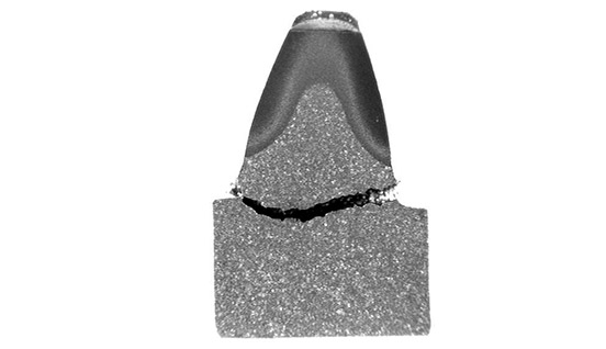
A carbon steel cogwheel, made of C43 (UNI 7847:1979, C45 according to EN 1.1194) that was installed on a machine tool has broken after few cycles and one of its teeth came off. This component had been induction hardened in order to increase the surface hardness and get a better performance in terms of mechanical properties and resistance to wear and fatigue.
The damaged component has been sectioned in several parts, in order to evaluate either the chemical composition complied the material composition as stated by the standard or not.
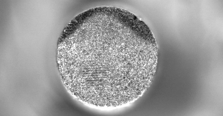
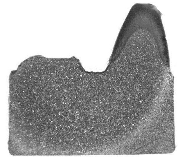
The darker region, in the upper external part, identifies the quenched area. Grip section of the tensile test specimen after breakup, polishing and Nital etch.
Chemical analysis made by spectrometryshowed conform results, including low sulphur and phosphorus concentrations, which means a good overall quality of the material under examination.

Hardness indentations layout both on broken and undamaged teeths.
The results have not shown any significant difference with the exception of the Y point in the detached tooth, whose hardness value is considerably higher than in the same region of the undamaged tooth.
The Y point is supposed to have acted as crack initiation point.
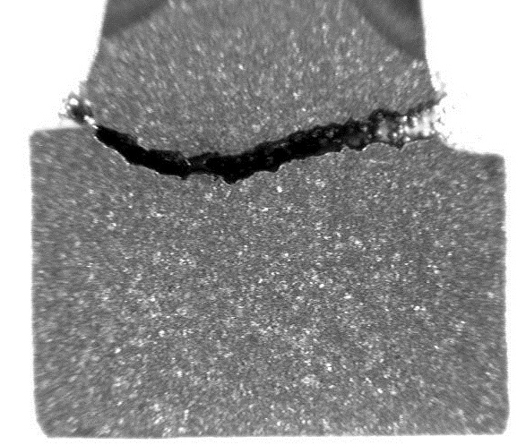
After evaluating the mechanical properties and chemical composition of the material, metallographic examinations have been made. In particular, several macrographic examinations have been made across the hardening layer.

PIC.1 e 2 Macrographs obtained in half thickness PIC.3 Macrograph obtained on the surface
According to the different industrial applications and service conditions for a gear, several hardening pattern may be listed. Here below some typical hardening patterns for cogwheels are reported (Heat Treatment of Metals, Wolfson Heat Treatment Centre, Aston University, Birmingham 2003.4, pp.97-103).

Pattern A, where just the flanks are hardened, is generally hazardous and refused; on the other hand, pattern I includes flank and root’s hardening and is often considered one of the best and most frequently adopted solutions. In particular this pattern is used for sprocket wheels and cogs with a diameter larger than 300 mm and spaced teeth. In fact, in these conditions this pattern combine good mechanical properties and resistance to fatigue, provided that surface hardness is not too high, becoming a source of embrittlement.
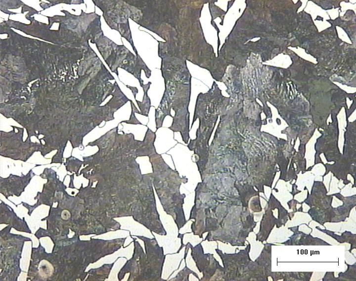
Following micrographic examinations have confirmed that fracture has occurred in the non-hardened region, that was characterised by a pearlitic-ferritic structure and large grain size, a configuration causing a brittle behavior of the material.

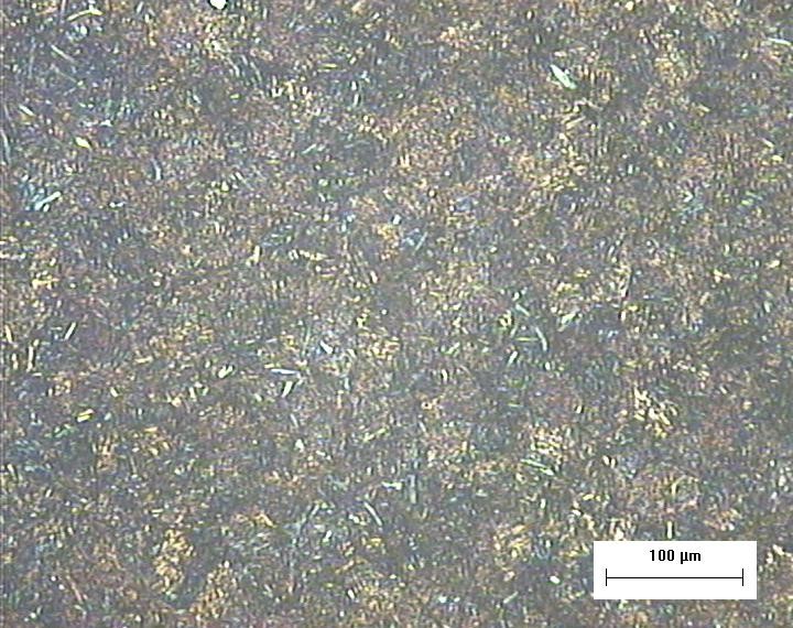
By contrast, the hardened region exhibits a martensitic structure (blue long strips) with finer grain and better mechanical properties.
Photomicrographs at 100x on tooth’s fillet and hardened region
To avoid that the same cracking mechanism occur again on other components, it would be recommended to adopt an induction hardening treatment able to provide a hardening pattern similar to those reported in the previous diagram (e.g. pattern I). The adoption of a regular control plan on the production based on periodic hardness measurement and macrographic examinations could help avoid this kind of problem in the future
EXPLODED GAS CYLINDER
Problem description
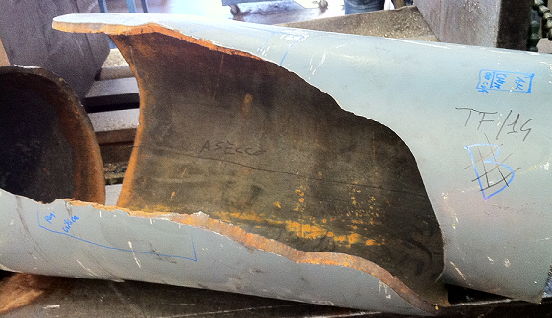
A gas cylinder made of 34CrMo4 (ASTM A29/A29M) has exploded few months after its installation. The explosion had opened it on the longitudinal axis.
When the accident occurred the gas plant was off, but the cylinder was charged.
Several portions of material have been sectioned from the damaged component, especially nearby the crack. The client has been asked to provide a new, undamaged cylinder, in order to make a comparison with the exploded one.
The internal surface examination has led to suppose that the fracture has derived from the propagation of an internal crack caused by a fatigue mechanism.
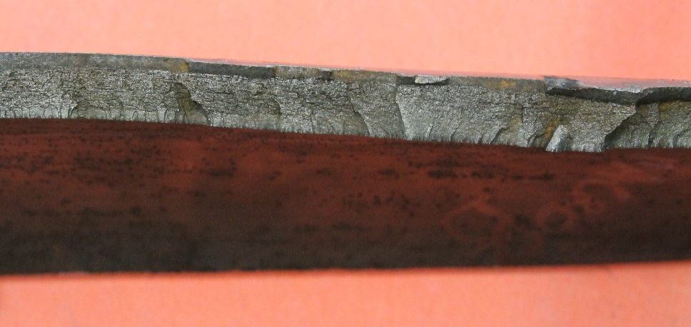
La sezione trasversale dell’area fratturata mostra segno di una cricca da fatica
Microscopic examination has detected signs of a pitting corrosion mechanism
(click here for more information about this kind of corrosion) and revealed several microcracks in the longitudinal direction.

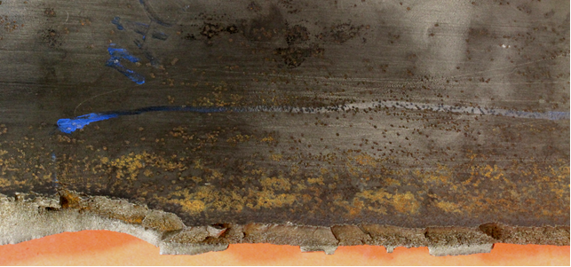
PIC.1 Pitting on the internal surface
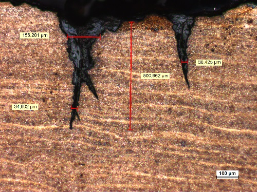
PIC.2 Cross-section shows the presence of pits and their depth
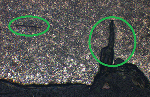
PIC.3 In addition to a pit, this photomicrograph shows a longitudinal microcrack (see green circled regions)
Two samples have been cut and machined from the damaged component: one from the corroded region and the other from a corrosion free area. Than the chemical composition of both has been analyzed by spectrometry. Nearby the corroded region high presence of sulphur has been found (its percentage was more than ten times higher than value reported in the material certificate).
The observation made with SEM has confirmed the elevated sulphur concentration and revealed high presence of iron and oxygen, elements that often characterize pitting corrosion products (e.g. iron sulfide, FeS, or iron III oxide, Fe2O3.)
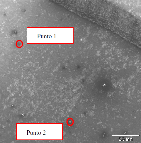
Microanalysis using Scanning Electron Microscope (SEM)
The tests and inspections carried out have proved that the fracture has been originated by the cylinder’s filling and emptying cyclic process, that is to say a fatigue crack; the crack causing the breakup was in the internal surface, nearby the cylinder’s bottom.
On the internal surface signs of pitting have been detected; their morphology could be connected to the hydrogen sulphide’s action (H2S).
These pits, that were easily visible in the cross-section, were not branched and not widened and the longitudinal microcraks, that were detectable by microscope, may not have been initiated by corrosion mechanisms (in fact they are not close to the corroded areas), quite the opposite they could be the consequence of residual stresses inside the material.

3D simulation of pitting mechanism (green) and longitudinal microcraks expansion (red) that contributed to the fracture.
It is safe to assume that the continuous filling of the cylinder with natural gas, containing H2S , and other substances rich in sulphur content, could have caused a pitting mechanism on the internal surface. The pits have probably entered in contact with some longitudinal microcracks deriving from residual stresses, generating a macrocrack that under the action of cyclic stresses has led to the fatigue failure of the component.
MORE INFORMATION
Ask a question or request a quote fulfilling the mask below
or call us at (+39) 0523 881 900
Required fields marked with *


